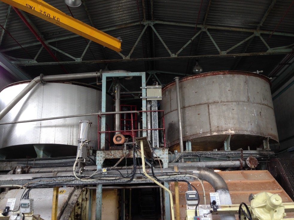
SM2079 - Paper Machine 1700 mm, Printing, writing & brown paper
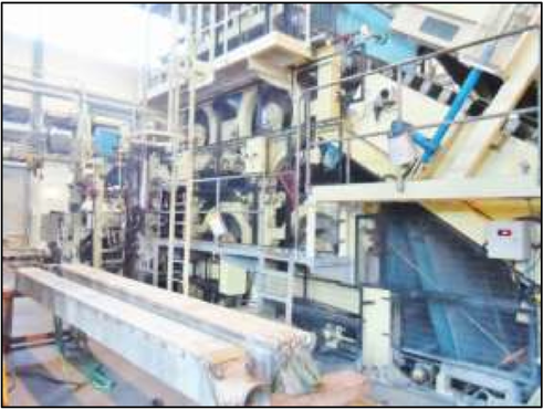
Paper machine: fourdrinier with long wire section for making writing and printing papers also brown papers.
Drive is on the right from the headbox. Year of build is 1962 by Bertrams Sciennes with various rebuilds over the years. All well maintained and in good condition. The dryer frames have internal vents for pocket ventilation in the dryer sections.
Production details:
- Deckle: 1690 to 1700mm
- Speed: 18 to 140 m/min
- Gsm: 50 to 285. Drive: line shaft with sectional drives to size press and pope reel.
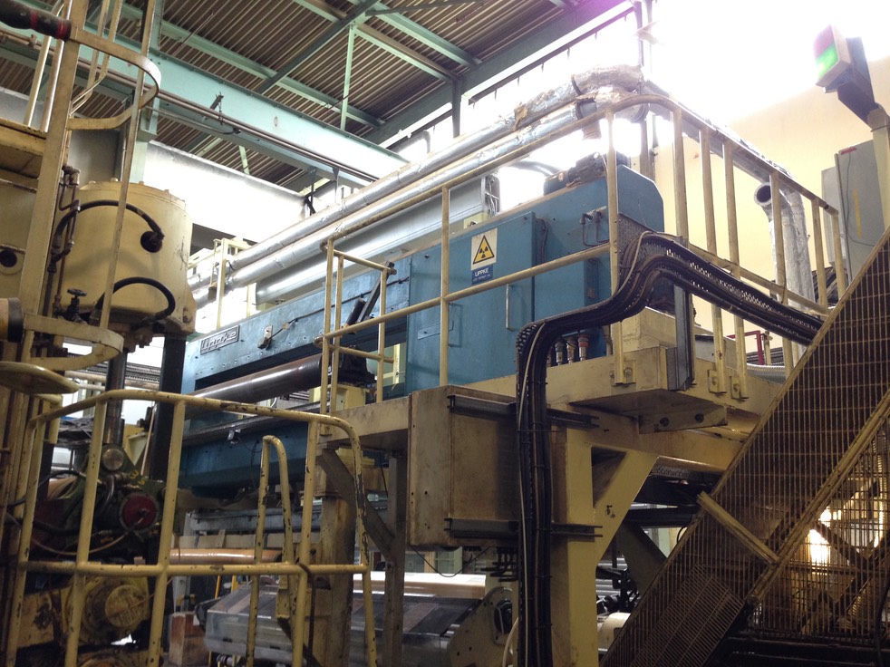
- QCS Lippke
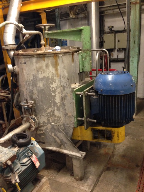
Stock preparation
Dunford stainless steel pulper: batch operation, 11,000 litres capacity. Grubbens rotor bottom mounted with perforated plate. Low consistency. Batch time 20/30 minutes, using 100% virgin pulp, two conveyors : one for virgin pulp, one for broke. Broke conveyor is on load cells, steam heating supply to the pulper.
Concrete chests with re-circulation pump.
Water tanks
Two stainless water tanks located above beaters. 15 m3 capacity each.
Six beaters with manual loading of the beater rolls.
Seven fibreglass tanks for chemical storage: unused at the moment.
Deculator
 Deculator by Clark and Vicario with Richard Berg first stage cleaners. Berg RB150 XC cleaners, RB80 LD cleaners. Year installed 2001.
Refiners
Six x Masson Scott midget refiners with manual loading. Solid cast rotors and stators with 3/16” bars.
Two x Strecker Finers with basalt fillings
Jylhava JCOO refiner.
All refiners with 75 kw motors
Two x stainless stock chests with side entry agitators
Machine pressure screen: stainless Finckh model 1 fitted with a basket with 0.25mm slots.
Pressure screen rejects to a Finckh vibrating screen in stainless width 1.5 mm holes.
The stock is heated to a temperature of 85% before being fed to the headbox.
Headbox / Wet End
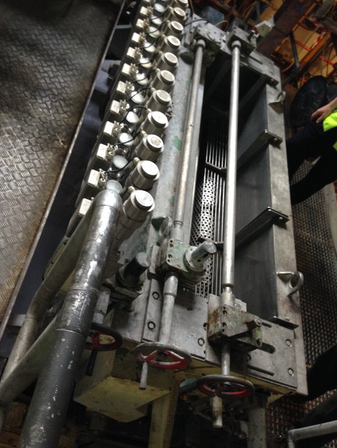
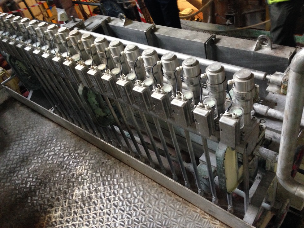
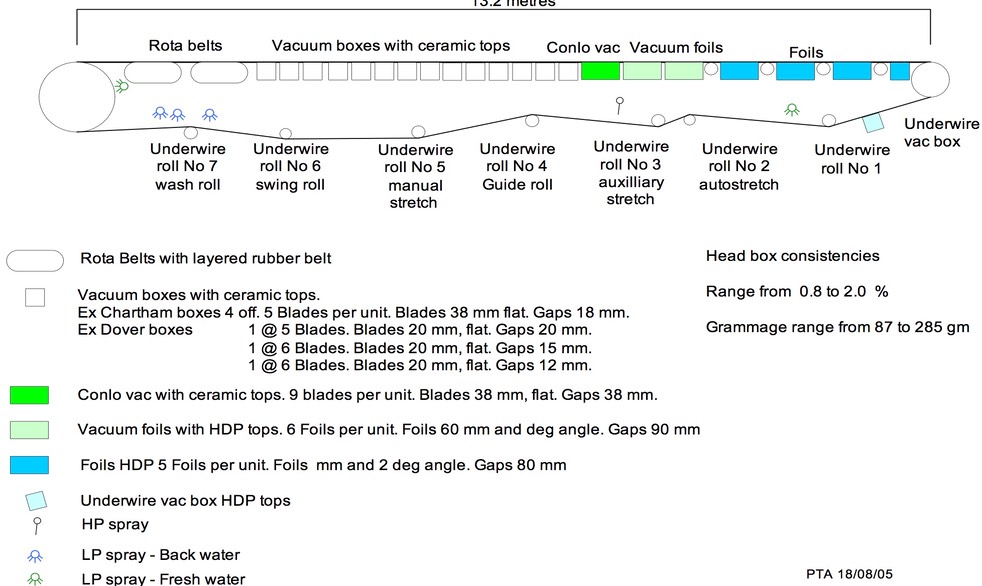
Kahula manufacture open headbox with taper inlet manifold, with recirculation, two evenor rolls, automatic slice control by Harmonic, slice width 2200mm, twenty auto slice lip adjusters for profile and grammage adjustment. Consistency range 0.8 to 2.0% and grammage range 87 to 285 gsm.
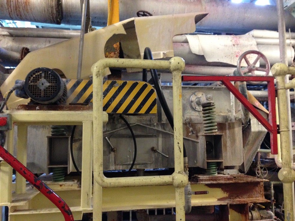
Cantilevered stainless wire frame. Bertrams shake motion on the breast roll. Thune wire guide and pneumatic wire tension unit.
Wire Shake
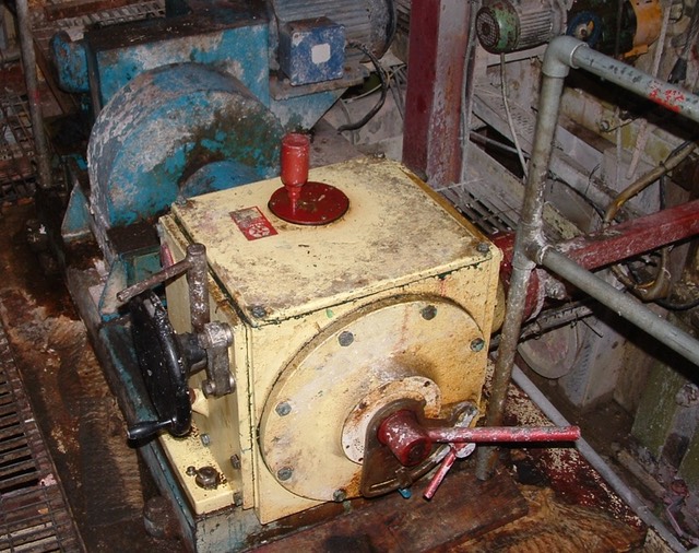
- The breast roll is shaken by a wire shake unit which allows a shake stroke from zero to a maximum of 22mm.
- The typical shake stroke currently used is in the order of 10 to 16mm.
- The breast roll, bearings and mounting mechanisms all move with the shake.
- The shake stroke is adjusted with the unit running by turning the regulating hand wheel on the side of the shake unit. Note there are now 3 locking mechanisms that need loosening before adjustment can take place.
- The shake stroke frequency may be varied from the pot on the control panel at the front side of the paper machine, which adjusts the rotational speed of the shake drive motor.
- The shake frequency is typically 180 to 200 strokes per minute. Pot settings 430 – 530.
- The maximum allowed stroke length reduces with increasing shake frequency; The faster the shake speed the shorter the stroke should be.
- If the shake stroke is too long or fast you will have problems with the grammage profile. Normally the profile will have a soft back edge
- If the shake stroke is too short or slow you will have problems with the grammage profile, sheet appearance and cross direction tear. Normally the profile will be very bumpy
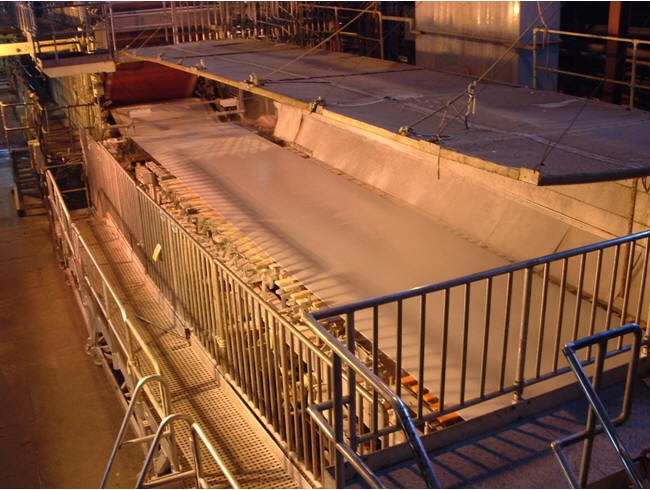
De watering comprising under wire vac box, four foil units, three Conolo vacuum foils, fourteen vacuum boxes and two Rotoformers. Millspaugh suction couch with blow off box for tail transfer.
Centres from Breast roll to Couch roll: 17 m. Wire length 29 m.
Consistency leaving wire: 18% at the couch
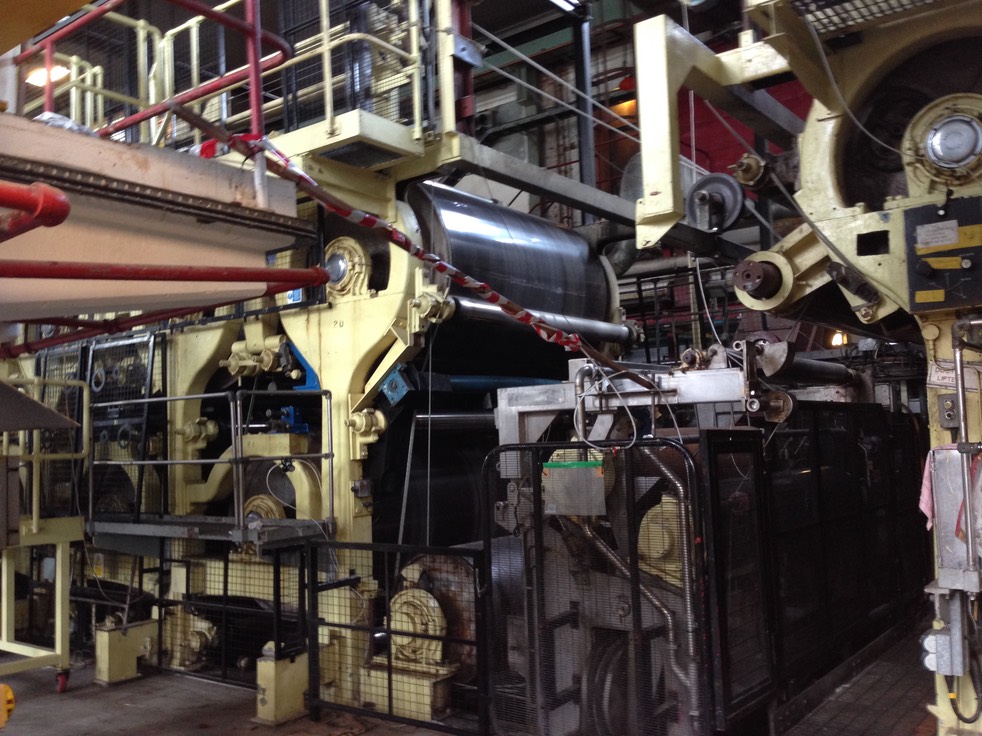
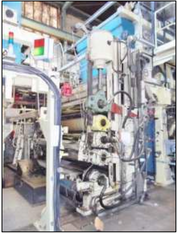
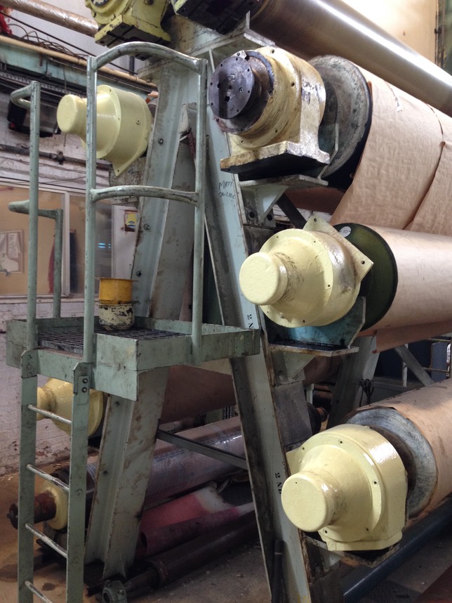
Press sections
Four through type presses with rope transfer, pneumatic loading. All bearings are A/F, automatic guides and manual felt tensioners. Press rebuilt 2001.
First press: top roll 585mm diameter, bottom roll 422mm diameter.
Second press: top roll 495mm diameter, bottom roll 442 mm diameter.
Third press: top roll 495 mm diameter, bottom roll 495mm diameter.
Fourth press: top roll 495mm diameter, bottom roll 422mm diameter.
Diagram and roll details available on request.
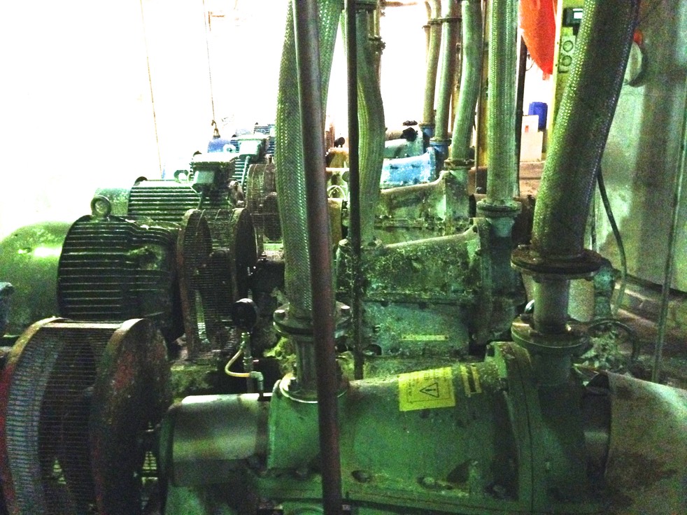
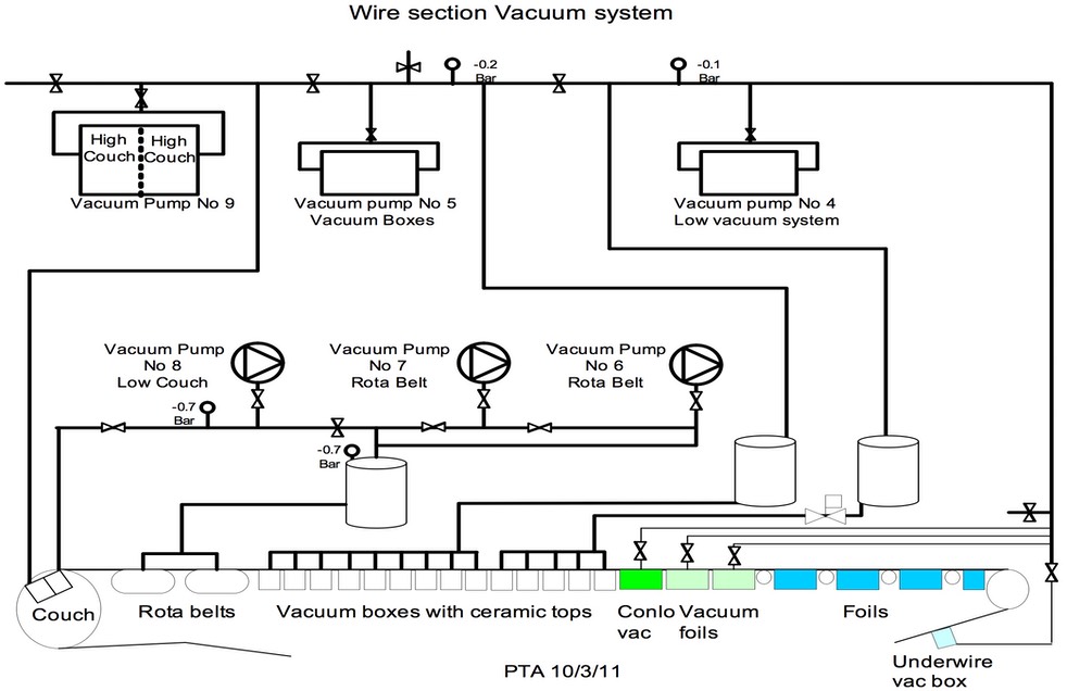
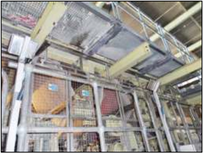
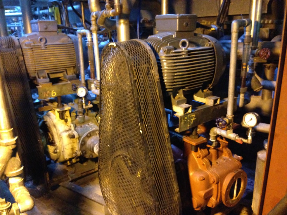
Vacuum pumps
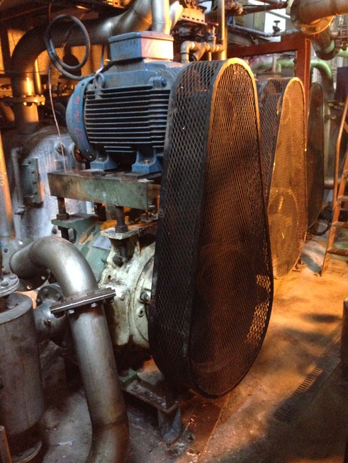
Vacuum pump number 9: Couch roll.
Vacuum pump number 10: 1st and 2nd top felt and blow boxes .
Vacuum pump number 11: 1st and 2nd bottom press felts.
Vacuum pump number 12: 3rd and 4th top and bottom press felts.
Vacuum pump number 13: 2nd top press felts.
Vacuum pump number 14: 3rd top press felts.
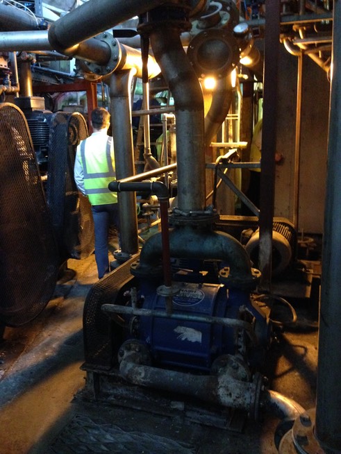
Two Nash 701 pumps, six Neypric pumps, Nash 2002 and three Nash 1401.
Drawing of vacuum system available on request.
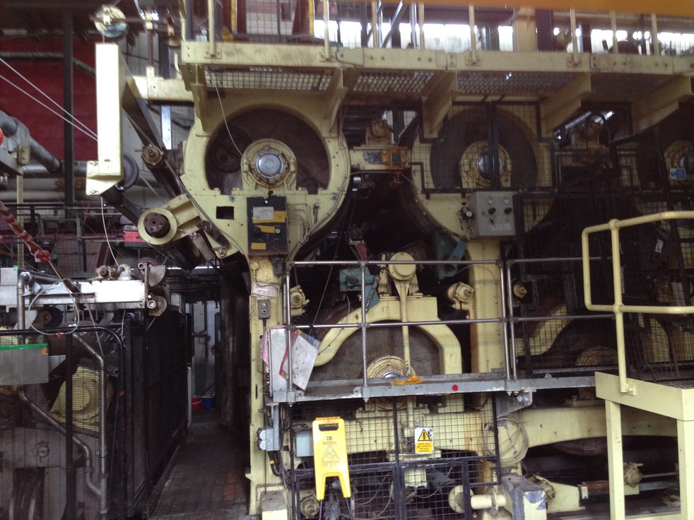
Dryer sections: first, second and third.
Date of construction: 1961. Hydraulic tested to 100 PSI in 1961. Current safe operating pressure 3.5 bar.
 Eighteen drying cylinders, diameter 1270mm, face 2175mm, sole plate centres 2845mm with internal bolted ends, scoops for condensate, steam and condensate on rear of dryers, A/F Copper split bearings. Huber felt guides, rope tail feeding and cylinders with rope grooves. Cylinders operating at 30 psi. Cylinder numbers 14, 16 and 17 fitted with press rolls to flatten paper profile. Pneumatic and weighted rope tensioners. Dryers are part gear drive and others felt driven, enclosed hood. This bank comprises the first three sections of dryers.
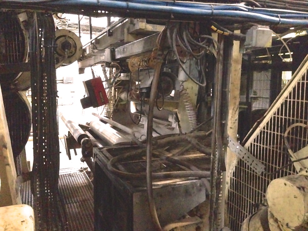
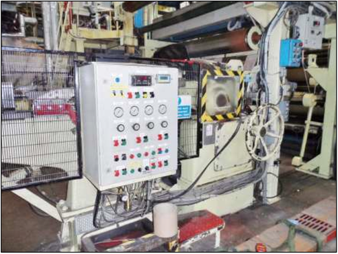
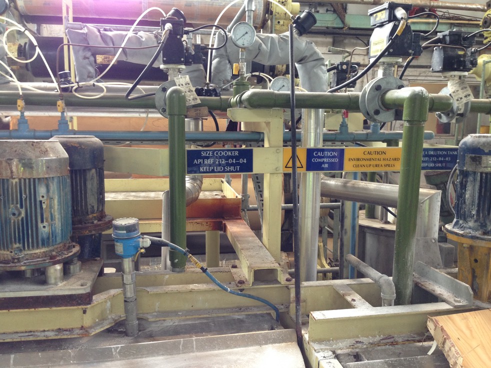
Size Press
 Inclined size press with pneumatic loading, sectional motor drives. Screen for size located under the size press. This press has rubber covered rolls bottom 500mm diameter rubber covered and top roll 500mm diameter microrock cover. Top roll doctored, starch applied by spray bars, application is surface sizing. Moisture sensor in line before size press.
Fourth drier section
Date of construction: 1961. Hydraulic tested to 100 PSI in 1961. Current safe operating pressure 3.5 bar. Face 2175mm, sole plate centres 2845mm.
Six drying cylinders, diameter 1270mm, with internal bolted ends, scoops for condensate, steam and condensate on rear of dryers. A/F Copper split bearings. Huber felt guides, rope tail feeding and cylinders with rope grooves. Cylinders operating at 30 psi. Cylinders numbers 14, 16 and 17 fitted with press rolls to flatten paper profile. Weighted rope tensioner. Dryers are part gear drive and others felt driven, enclosed hood.
Size press (bath type)
Vertical size press pneumatic loading, sectional motor drives.
Screen for size located under the size press.
This is a bath type size press where the sheet passes through a bath and surplus
size removed by press rolls, bottom roll 435mm diameter with rubber cover and
top roll 500mm diameter fitted with a Microck cover and is doctored .
Moisture sensor in line before size press.
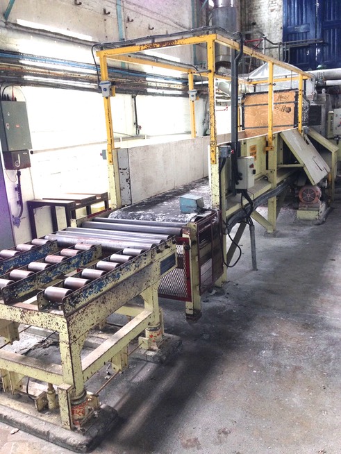
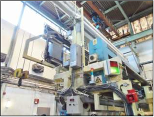
Air Drier
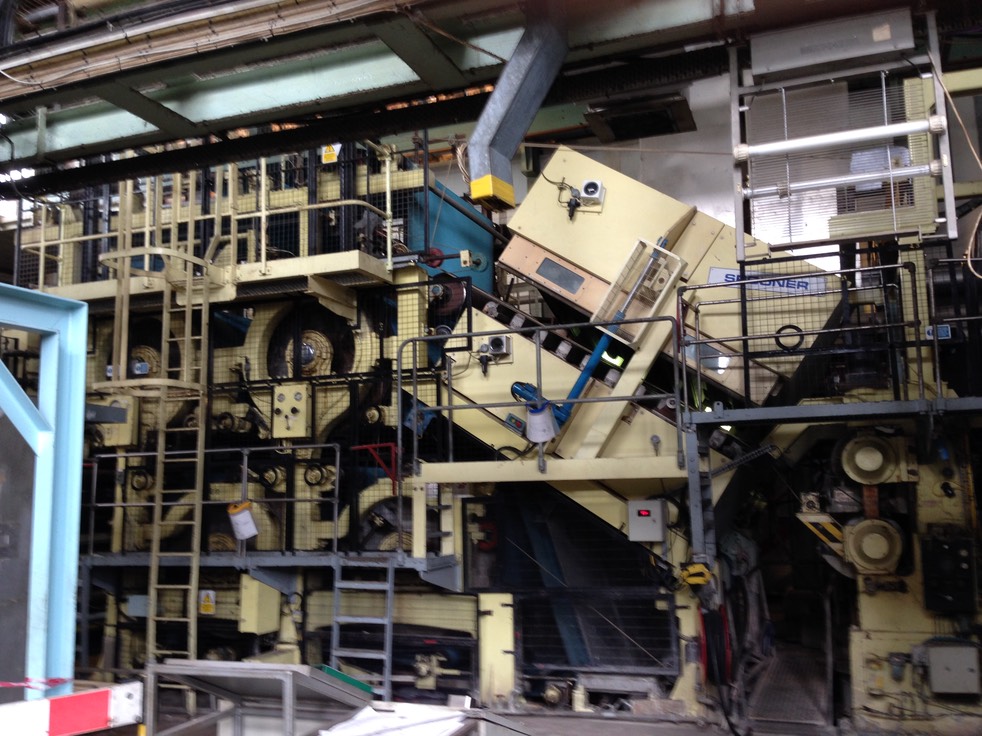
Spooner air hood inclined. Year 2000. Air blow to both sides of the paper.
The steam pressure is 2.0 bar and maximum temperature 114 Deg C.
Camber roll after air dryer.
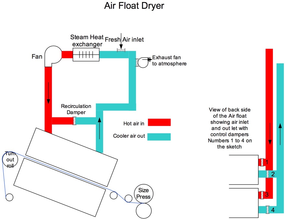
Air is heater by passing through a Steam / Air heat exchanger.
The temperature of the air is controlled by the DCS by adjusting the amount of steam going to the heat exchanger. With a steam
pressure of 2.0 bar the maximum temperature achievable is 11°4C
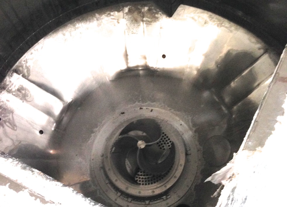
The fan blows the air to the Air Float. The amount of air is controlled by dampers in the duct work [1 & 3 on the sketch].
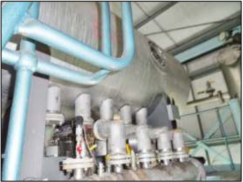
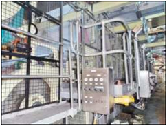
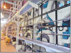
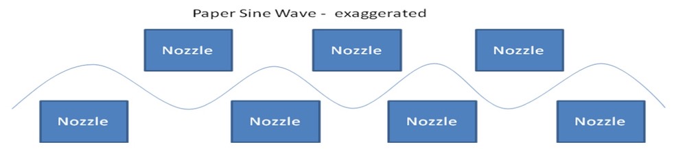
Inside the Air Float the air is directed onto the top and bottom of the paper by a series of nozzles. These nozzles are off set so that the paper creates a sine wave as it goes through the dryer. See photographs below.
The nozzles at either end of the air float dryer are designed to reduce the end spill of air out of the air float. See photograph
below
The other nozzles are designed with 2 small slots across the width so that the air impinges evenly onto the sheet .See
photograph below
The air is then removed by the suction side of the fan through more control dampers that are fully open in normal running [ 2 & 4
on the sketch] The removed air goes through the heat exchanger again and back to the Air Float Dryer.
An exhaust fan removes some of this recirculation air and discharges it to atmosphere. The amount of discharge is controlled by
manual dampers near the fan unit. A small amount of replacement fresh air is allowed into the system. This replacement air is
controlled by manual dampers near the fan unit. These two sets of dampers allow the control of moisture in the recirculation air
and of the the amount of air spill in and around the air float.
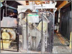
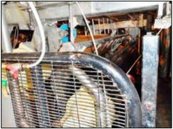
When “Tail Feeding” the air float dryer opens up on the front side to allow access. [Like a Clam] When tail feeding the Air Float or at start up the air is put onto “Recirculation” The control dampers [1 to 4] on both in coming or out going air are nearly closed and the recirculation damper is open. This allows the majority of the air to by-pass the air float.
The air pressure in the top and bottom sections of the air float dryer can be varied independently to give control in the dryer. If the air pressure are incorrectly set the paper can touch the nozzles causing scratch lines on the paper. Or other run ability problems
The Turn Out roll after the Air Float dryer is critical in controlling the paper with in the dryer. The speed of this roll can be altered so that it is different to that of the paper. This speed relationship to the paper and the tightness of the draws before and after the dryer are the main controlling factors.
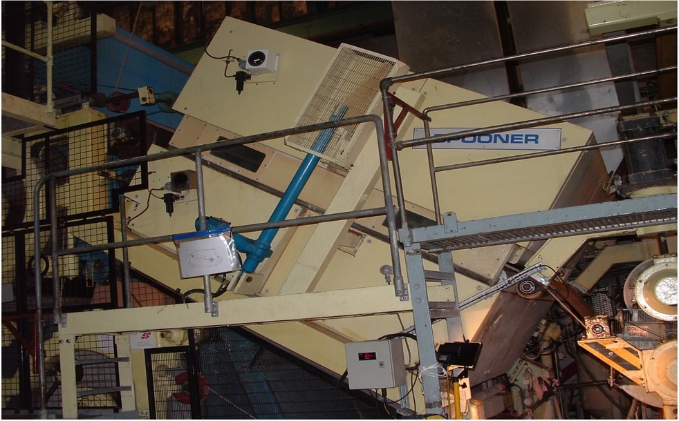
Air float drier closed
Fifth drier section
 Date of construction: 1961. Hydraulic tested to 100 PSI in 1961. Current safe operating pressure 3.5 bar.
Four drying cylinders, diameter 1270mm, with internal bolted ends, scoops for condensate, steam and condensate on rear of dryers. A/F Copper split bearings. Huber felt guides, rope tail feeding and cylinders with rope grooves. Cylinders operating at 30 psi. Cylinder numbers 14, 16 and 17 fitted with press rolls to flatten paper profile. Weighted rope tensioner. Dryers are part gear drive and others felt driven, enclosed hood.
Dryers are in sections:
1st 1 to 6 dryers
2nd 7 to 12
3rd 13 to 18
4th 19 to 26. This includes the small pony dryer after the size press.
Calender
Hunt and Moscrop vertical calender: five roll stack.
Two Kuster rolls: top and bottom positions.
Three intermediate rolls with a Johnson water heating unit.
A/F bearings, hydraulic loading.
All rolls are doctored.
Calcoil unit for profiling.
Pope reel and Control Systems
 Honeywell fault detector, year 2010 (no cameras).
Lippke scanner measuring profile, gsm, moisture.
Macbeth in line colour monitoring unit, year 2005.
In line slitting section for edge trims with adjustable Tidland slitters, installed
2001.
Horizontal pope reel with manual reel transfer for new reels, pneumatic loading on
secondary arms. Pope reel on expanding bars. Manual tape turn-up system.
Reel bar extraction unit and reel bar transporter for returning bars to the paper
machine.
Spares
Spare roll list is available on request.
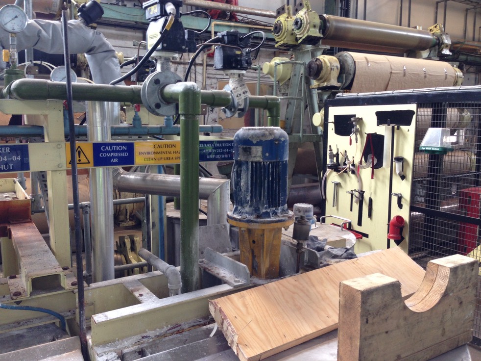
Preparation Area Opposite the Machine
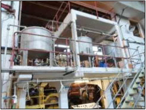 Tanks for the preparation of starch and acid for the paper machine.
Product prepared stored in three elevated stainless tanks located above the
centre isle of the paper machine.
Paper broke handling.
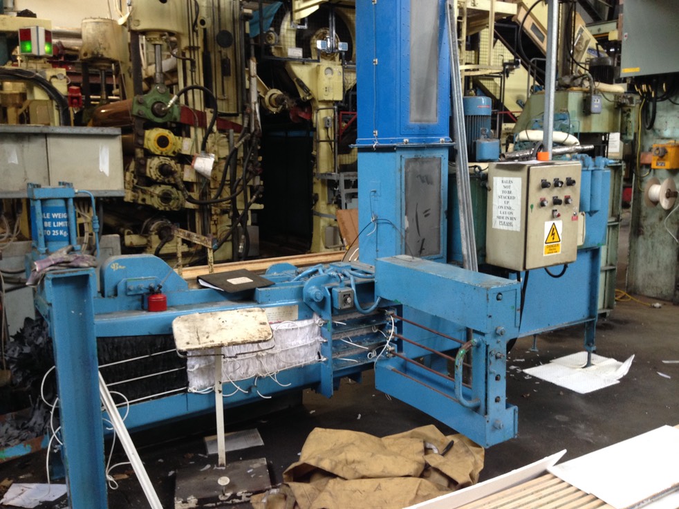
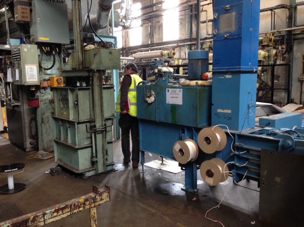
Two balers: one vertical with electric top loading. Other press fed from cyclone which is of hydraulic operation with auto/manual tying of bales.